Journal of Cancer
ISSN: 1837-9664
3.2
Impact Factor
ISSN: 1837-9664

 Global reach, higher impact
J Cancer 2018; 9(20):3683-3689. doi:10.7150/jca.27220 This issue Cite
Research Paper
How much margin do we need for pelvic lymph nodes irradiation in the era of IGRT?
Zhikai Liu*, Xia Liu*, Fuquan Zhang, Ke Hu ![]()
Department of Radiation Oncology, Peking Union Medical College Hospital, Chinese Academy of Medical Sciences & Peking Union Medical College, Beijing, China.
* These authors contributed equally to this work
Received 2018-5-12; Accepted 2018-7-5; Published 2018-9-8
Citation:
Liu Z, Liu X, Zhang F, Hu K. How much margin do we need for pelvic lymph nodes irradiation in the era of IGRT?. J Cancer 2018; 9(20):3683-3689. doi:10.7150/jca.27220. https://www.jcancer.org/v09p3683.htm
Other stylesAbstract
Background and purpose: Image guided radiotherapy (IGRT) without 6 degree of freedom couch can only correct the translational setup errors of pelvic radiotherapy. But errors introduced by rotation and deformation of CTV can't be adjusted in most of IGRT systems. This article is to evaluate these errors and to provide recommendations on the margin needed in the era of IGRT.
Material and methods: 218 patients who received pelvic radiotherapy in PUMC Hospital from 2012 to 2014 were included. A simulation CT and a CBCT were acquired for every patient. 3D and 6D registrations of CT and CBCT were applied. 9 bony landmarks were marked and distances of each landmark between CT and CBCT were measured in three directions.
Results: Without image guidance, movements of landmarks in the directions of LR, AP and SI were 0.4 ± 2.5 mm, 1.3 ± 3.8 mm and 1.5 ± 5.0 mm respectively, with 3D-registration, movements were 0.0 ± 1.5 mm, 0.7± 2.8 mm and 0.6± 3.2 mm, and with 6D-registration, movements were 0.0 ± 0.5 mm, 0.2 ± 1.0 mm and 0.2 ± 1.1 mm in each direction.
Conclusions: IGRT could reduce setup errors. IGRT with 6D treatment couches could further reduce setup errors compared to 3D couches. For centers without IGRT, we suggest CTV-PTV margins of 6 mm, 9 mm and 12 mm in LR, AP and SI directions respectively, margins of 3 mm, 6.5 mm and 7 mm for the use of daily IGRT with 3D couch and 2 mm, 3 mm and 3 mm for 6D couch.
Keywords: Pelvic lymph nodes, irradiation, image guided radiotherapy (IGRT)
Introduction
Pelvic lymph nodes are commonly involved in many cancers [1-3], such as prostate cancer, rectum cancer, cervical cancer, endometrial cancer, and bladder cancer etc. For a great proportion of these cancers, pelvic lymph node radiation is the standard of care.
Intensity-modulated radiation therapy (IMRT) has been used for pelvic lymph node treatment because of its outstanding risk organ protection. Dosimetric reports show significantly reduced doses to bowel, rectum, bladder and bone marrow with IMRT compared with conventional radiotherapy techniques [4-5]. The complex dose distributions achieved with IMRT, of relatively steep dose gradients, show that enough margins should be added to clinical target volume (CTV) to avoid potential geographical miss. However, the large margins from clinical target volume (CTV) to planning target volume (PTV) weaken the dosimetric advantages [6].
The margin between CTV and PTV consists of: the internal margin, which accounts for organ motion, and the setup margin, which accounts for patient setup and delivery errors. For lymph node CTV, the internal organ motion is minimal and the majority part of CTV-PTV margin is the setup margin. Image-guided radiotherapy (IGRT), with various types of pre-treatment image guidance, aims to reduce geometric uncertainty. However, in most of IGRT systems, only the translational motions could be corrected, while the rotational motions and CTV deformations (caused by deformations of organs) could not be corrected. Adaptive radiotherapy (ART) attempts to overcome the uncertainties caused by organ motion, by on-line or off-line replanning [7], but ART usually takes lots of time and is unsuitable for high throughput centers. The most practical strategy is still to add a CTV-PTV margin.
Clinical target volume of pelvic lymph nodes is usually defined as certain distances around blood vessels [8], and it is presumed that most of the pelvic vessels have a relatively stable position to the bony structures. Matching to bone is probably sufficient for pelvic lymph node CTVs as they are not thought to move to the pelvic side walls. But the bony pelvis is not totally rigid, which means it may have slight deformation between two delivery fractions, so a small CTV-PTV margin should be added to compensate for the deformation of bony pelvis.
However, few studies had addressed the pelvic deformation or the CTV-PTV margin of pelvic lymph nodes with daily IGRT. This study is to quantify the deformation and rotation of bony pelvis by measuring the residual movements of 9 landmarks on bony pelvis after rigid registration and to provide recommentations on CTV-PTV margin of pelvic lymph nodes with or without IGRT.
Patients and methods
Patients
In this study, we retrospectively enrolled 218 patients with various cancers who received pelvic radiotherapy at Peking Union Medical College Hospital between Aug. 2012 and May. 2014. 41 patients were male and 177 were female. Table 1 shows the diseases distribution.
Table 1
Diseases distribution
| Diseases | Number |
|---|---|
| Cervical cancer | 148 |
| Rectum cancer | 37 |
| Ureteral and Bladder cancer | 16 |
| Uterine neoplasms | 7 |
| Prostate cancer | 7 |
| others | 3 |
Immobilization
To facilitate daily patient accurate positioning, HipFix baseplate immobilization system (CIVCO, Orange City, Iowa, USA) was indexed on the treatment couch (Varian Medical Systems, Palo Alto, CA, USA). Patients lied on the baseplate in the supine position with thermoplastic trunk mask immobilization (Renfu Medical, Guangzhou, China). Tattoos on the patients' skin were used with treatment room lasers to assist in daily setup.
Simulation
All patients underwent simulation computer tomography (CT) scan in the supine position with thermoplastic trunk mask immobilization (Renfu Medical, Guangzhou, China). The CT scans were obtained from L4 vertebral body to 2 cm below the ischial tuberosities. Linear interpolation method [9] was used to enhance image resolution. The clinical target volume (CTV) for each patient was contoured and dose was prescribed by radiation oncologists according to guidelines of specific disease. Treatment plans were created with Eclipse treatment planning software.
Image Registration
Before the first treatment, an on-board cone beam CT (CBCT) was acquired and rigid registration between simulation CT and CBCT was applied. First an automatic 3D rigid registration (only the translational corrections) was done by Eclipse treatment planning software. Then attending radiation oncologist reviewed the automatic rigid registration result and made adjustment if necessary. 3D rigid registration results were recorded and applied for treatment. Additional 6D rigid registrations (both translational and rotational corrections) were performed off-line.
Bony landmarks
Nine bony landmarks were selected.
1. Right anterior superior iliac spine
2. Left anterior superior iliac spine
3. Right ischial spine
4. Left ischial spine
5. Top of right acetabulum
6. Top of left acetabulum
7. Anterior superior margin of the 1st sacrum
8. Inferior tail bone
9. Superior margin of pubic symphysis
Figure 1 and figure 2 show distributions of the nine landmarks. These landmarks were marked on both simulation CT and CBCT with carefully reviewed of images on axis, coronal and saggital planes.
Measurement repeatability
To evaluate the reproducibility of our method of measurement, landmarks' locations of the first 10 patients were measured twice by the same investigator with one week interval for both CT and CBCT images.
Figure 1
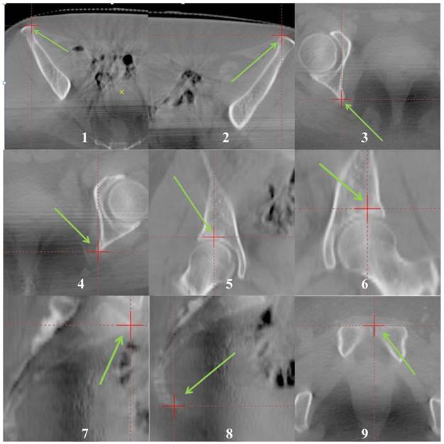
Anatomical Positions of the nine bony landmarks. They were marked with red “+” and green arrows. The landmarks could be easily recognized in both CT and CBCT images.
Setup errors
All images were in a 3-dimensional coordinate system, the origin of coordinates is the center of CTV. X, Y and Z of the coordinates stand for the directions in left-right (LR), anterior-posterior (AP), and superior-inferior (SI) directions respectively. Coordinates of landmarks on simulation CT were recorded as L1 (X1, Y1, Z1). Movements of CBCT in the 3D registration were recorded as M (Xm, Ym, Zm). Locations of landmarks on CBCT based on 3D registration with simulation CT were recorded as L2 (X2, Y2, Z2). Locations of landmarks on CBCT based on 6D registration with simulation CT were recorded as L3 (X3, Y3, Z3).
We used vectors “ER-ng (Errors with no guidance) = L2-L1-M (X2-X1-Xm, Y2-Y1-Ym, Z2-Z1-Zm)” to evaluate the setup errors of each landmark without any image guidance. Similarly, “ER-3D (Errors after 3D-registration) = L2-L1 (X2-X1, Y2-Y1, Z2-Z1)” was used to evaluate the residue errors of landmarks after a 3D-registration and “ER-6D (Errors after 3D-registration) = L3-L1 (X3-X1, Y3-Y1, Z3-Z1)” for the 6D-registration.
Statistical analysis
Mean value and standard deviation (SD) of each landmark errors for all patients were calculated.
It is assumed that landmark errors for each patient were independent and followed an approximate Gaussian distribution. For Gaussian distribution, z* is used as the critical value, and Φis the cumulative distribution function of the Gaussian distribution. This value is only dependent on the confidence level for the test. When the confidence interval is 95%, z* is 1.96[10].
So the formula “Mean + 1.96 SD” was used to estimate the 95% confidence interval for the CTV-PTV margins. Correlation analyses were applied between movements of landmarks.
Figure 2
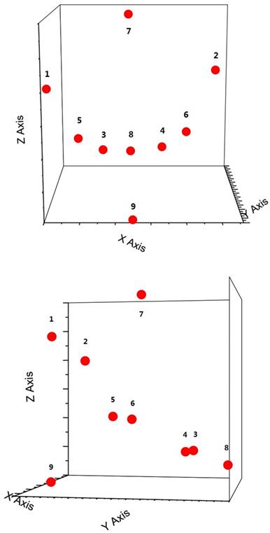
3D distributions of the nine bony landmarks. The landmarks were roughly uniformly distributed in the pelvis.
Results
To evaluate reproducibility, landmarks' locations of 10 patients were measured twice with an interval of one week. The average location difference between two measurements were 0.1 ± 0.4 mm in LR and AP directions, and 0.1 ± 0.6 mm in SI direction for both CT and CBCT images.
One CT and one cone beam CT were taken for all the 218 patients. Figure 3 shows the histograms of average movements of 9 landmarks for the three axes in which the errors were reduced with image guidance of 6D-registrations.Without image guidance, the average movements of landmarks in LR, AP and SI directions were 0.4 mm, 1.3 mm and 1.5 mm respectively. The average standard deviations of landmarks' movements were 2.5 mm, 3.8 mm and 5.0 mm in each direction. With 3D-registration, the average movements of landmarks were 0.0 mm, 0.7 mm and 0.6 mm in LR, AP and SI directions respectively. The average standard deviations of landmarks' movements were reduced to 1.5 mm, 2.8 mm and 3.2 mm in each direction. With 6D-registration, the average movements of landmarks were 0.0 mm, 0.2 mm and 0.2 mm in LR, AP and SI directions respectively. The average standard deviations of landmarks' movements could be further narrowed to 0.5 mm, 1.0 mm and 1.1 mm in each direction. Table 2 shows details of landmarks' movement.
Using the formula “Mean + 1.96 SD”, the margins needed to compensate for 95% of movements in LR, AP and SI directions were 5.3 mm, 8.8 mm and 11.2 mm without image guidance, 3.0 mm, 6.3 mm and 6.9 mm with 3D-registration, and 1.0 mm, 2.1 mm and 2.2 mm with 6D-registration respectively.
Table 2
Movement of landmarks
| No. | Movements(Mean ± SD) (mm) | ||||||||
|---|---|---|---|---|---|---|---|---|---|
| Without Guidance | 3D-registration | 6D-regestration | |||||||
| LR | AP | SI | LR | AP | SI | LR | AP | SI | |
| 1 | -0.36±2.49 | -0.77±3.86 | 0.95±5.47 | -0.01±1.47 | -0.23±2.84 | 0.09±3.91 | -0.02±0.45 | -0.13±1.07 | 0.03±1.26 |
| 2 | -0.91±2.56 | -2.03±3.61 | 1.92±5.24 | -0.56±1.60 | -1.49±2.61 | 1.05±3.54 | -0.21±0.61 | -0.43±1.06 | 0.32±1.19 |
| 3 | -0.16±2.41 | -1.13±3.80 | 0.79±4.66 | 0.19±1.31 | -0.59±2.81 | -0.07±3.07 | 0.06±0.42 | -0.13±0.96 | 0.05±0.81 |
| 4 | -0.30±2.41 | -1.78±3.61 | 1.10±4.58 | 0.05±1.41 | -1.24±2.57 | 0.24±2.85 | 0.01±0.49 | -0.26±0.93 | 0.07±1.02 |
| 5 | -0.25±2.29 | -0.69±4.06 | 1.71±5.14 | 0.09±1.17 | -0.15±3.05 | 0.84±3.41 | 0.05±0.44 | -0.07±0.95 | 0.27±1.23 |
| 6 | -0.39±2.39 | -1.89±3.74 | 2.16±4.92 | -0.05±1.32 | -1.35±2.83 | 1.29±2.99 | -0.04±0.39 | -0.33±0.92 | 0.34±1.01 |
| 7 | -0.38±2.66 | -1.13±3.66 | 1.76±4.80 | -0.03±1.74 | -0.59±2.39 | 0.90±2.90 | -0.03±0.51 | -0.13±0.90 | 0.26±1.05 |
| 8 | 0.04±2.81 | -0.96±3.90 | 0.80±4.95 | 0.38±1.94 | -0.43±2.90 | -0.07±3.13 | 0.13±0.61 | -0.08±1.04 | -0.02±0.97 |
| 9 | -0.74±2.50 | -1.49±4.02 | 1.95±5.07 | -0.39±1.44 | -0.96±3.16 | 1.09±3.20 | -0.09±0.45 | -0.15±1.01 | 0.26±1.00 |
Discussion
Pelvic lymph node irradiation is the standard of care for many malignant tumors such as cervical cancer, prostate cancer and rectum cancer. The lymph node CTVs were usually defined by adding a certain margin from main blood vessels. It is presumed that the major pelvic vessels have a relatively stable position to the bony pelvis, so it is feasible to use bony landmarks as substitutes to measure the movements of pelvic lymph node CTV. 9 bony landmarks were selected due to easy recognition in CT and CBCT thus the observer errors could be minimized. The pretest results showed that our repeat error would be about 1 mm. These landmarks were widely and roughly uniformly distributed all over the pelvis, so movements of landmarks could represent the movement of different parts of pelvis and thus the different part of CTV. Please note that this paper focuses on only the lymph node CTV, motions of organs such as rectum, bladder and small bowels are beyond the scope of this study.
Figure 3
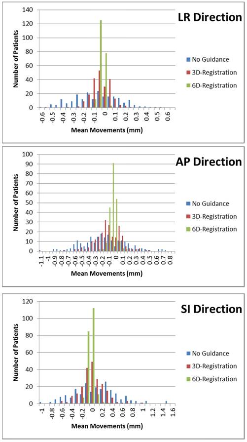
Histograms of the average movements of 9 landmarks for all 218 patients along the LR, AP and SI axes.
A CTV-PTV margin is needed to compensate for the setup errors. In our study, with IGRT, the average movement is less than 1.5 mm in each direction. However, standard deviations of landmarks' movements were relatively large, which were 2.3 - 2.8 mm in LR direction, 3.6 - 4.1 mm in AP direction and 4.6 - 5.5 mm in SI direction. And we suggest margins of 6 mm, 9 mm and 12 mm for LR, AP and SI directions. The margin for SI direction was larger compared with LR direction. We speculated it might be due to the HipFix baseplate and thermoplastic trunk mask immobilization system which was cylinder-shaped and seemed not as good fixation in SI direction as in other directions.
IGRT is useful to minimize setup errors in each treatment delivery fraction, but it is impossible to completely eliminate the errors. In most of IGRT systems, only translational setup errors could be corrected. Pastore et al. [11] found that correcting rotational errors by couch translations can lead to dosimetric uncertainties in the dose to organs at risk. We evaluated the residue errors by measuring the landmarks' movement after 3D-registrations were preformed. Movements of landmarks (residue errors) were reduced with the standard deviations among 1.2 - 1.9 mm, 2.4 - 3.2 mm and 2.8 - 3.9 mm in LR, AP and SI directions respectively. And we suggest margins of 3 mm, 6.5 mm and 7 mm in each direction for the use of daily IGRT with 3D treatment couch.
The residue errors might be due to rotations and deformations of CTV. Rotational setup errors didn't cause much trouble when the target was small. But for pelvic radiotherapy, CTV could be as large as 20 cm in diameter, and then a 1 degree of rotation around the isocenter could cause 1.7 mm movement at the edge of CTV. Ahmad et al. [12] showed significant rotational setup variations of the pelvis around the pitch axis. 6D treatment couch can be rotated around three orthogonal axes, which are yaw, pitch, and roll rotations, so the rotational setup errors could also be corrected and less residue errors were expected with 6D treatment couch. Our results support the hypothesis. Standard deviations of landmarks' movements were further narrowed to 0.4 - 0.6 mm in LR direction, 0.9 - 1.1 mm in AP direction and 0.8 - 1.3 mm in SI direction with 6D treatment couch. These movements were small and comparable with the measurement accuracy of our study and machine accuracy of IGRT system. In consideration of the measurement and machine accuracy, we suggest margins of 2 mm, 3 mm and 3 mm in each direction for the use of daily IGRT with 6D treatment couch.
Residue errors after 6D-registration might due to deformations of CTV. Pelvic bones were relatively rigid so the deformable errors were quite small compared with CTV. It might be different for CTVs outside the pelvis, for example, flexibility of cervical vertebra may cause more deformable setup errors for head and neck CTVs [13, 14]. Those errors were difficult to correct. Adaptive radiotherapy (ART) might be a solution and further validation of ART is required.
In our center, patients were treated in supine position and fixed with HipFix baseplate and thermoplastic trunk mask immobilization system. Although prone position has been shown to reduce small bowel within the treatment field [15,16], it is also associated with considerable set-up errors (up to 15 mm) caused by pitch sacral rotations (-14°to 11.5°) [17]. Siddiqui et al. [18] analyzed prone and supine patient setup errors. Systematic setup errors in prone setup were larger than in supine setup. It probably negates the benefits of small bowel sparing by increasing PTV margins to account for these errors, and Ahmad et al. [19] found 6D treatment couch might solve this problem. Further studies need be done for different patient positions and immobilizations.
In this study, each patient only had one CBCT scan, because we were not sure how much margin could be reduced with IGRT and the concern of extra radiation due to daily CBCT. Further prospective studies are on-going for small CTV-PTV margins with multiple CBCT scans in our center.
Conclusions
IGRT could reduce errors caused by setup processes and 6D treatment couches could further reduce setup errors compared to 3D couches. For pelvic radiation, residue errors of about 1-2 mm exists which might be due to the deformations of CTV. For centers without IGRT, we suggest margins of 6 mm, 9 mm and 12 mm in LR, AP and SI directions respectively, margins of 3 mm, 6.5 mm and 7 mm for the use of daily IGRT with 3D treatment couch and margins of 2 mm, 3 mm and 3 mm for the use of daily IGRT with 6D treatment couch in each direction.
Competing Interests
The authors have declared that no competing interest exists.
References
1. Small-W J, Mell L P, Creutzberg C. et al. Consensus guidelines for delineation of clinical target volume for intensity-modulated pelvic radiotherapy in postoperative treatment of endometrial and cervical cancer. Int J Radiat Oncol Biol Phys. 2008;71(2):428-434
2. Roels S, Duthoy W, Haustermans K. et al. Definition and delineation of the clinical target volume for rectal cancer. Int J Radiat Oncol Biol Phys. 2006;65(4):1129-1142
3. Sargos P, Guerif S, Latorzeff I. et al. Definition of lymph node areas for radiotherapy of prostate cancer: A critical literature review by the French Genito-Urinary Group and the French Association of Urology (GETUG-AFU). Cancer Treatment Reviews. 2015;41(10):814-820
4. Roeske JC, Lujan A, Rotmensch J. et al. Intensity-modulated whole pelvic radiation therapy in patients with gynecologic malignancies. Int J Radiat Oncol Biol Phys. 2000;48(5):1613-1621
5. Portelance L, Chao KS, Grigsby PW. et al. Intensity-modulated radiation therapy (IMRT) reduces small bowel, rectum, and bladder doses in patients with cervical cancer receiving pelvic and para-aortic irradiation. Int J Radiat Oncol Biol Phys. 2001;51(1):261-266
6. Ahamad A, D'Souza W, Salehpour M. et al. Intensity-modulated radiation therapy after hysterectomy: comparison with conventional treatment and sensitivity of the normal-tissuesparing effect to margin size. Int J Radiat Oncol Biol Phys. 2005;62(4):1117-1124
7. Anne V, Ludvig M, Jimmi S. et al. Adaptive plan selection vs. re-optimisation in radiotherapy for bladder cancer: A dose accumulation comparison. Radiother Oncol. 2013;109(3):457-462
8. Shih H, Harisinghani M, Zietman AL. et al. Mapping of nodal disease in locally advanced prostate cancer: Rethinking the clinical target volume for pelvic nodal irradiation based on vascular rather than bony anatomy. Int J Radiat Oncol Biol Phys. 2005;63(4):1262-1269
9. Park SC, Park MK, Kang MG. Super-resolution image reconstruction: a technical overview. IEEE Signal Process Mag. 2003;20(3):21-36
10. Deborah J. Rumsey. Checking Out Statistical Confidence Interval Critical Values - For Dummies. www.dummies.com. Retrieved. 2016 -02-11
11. Pastore G, Casamassima F, Menichelli C. et al. Correcting Rotational Errors by Couch Translations can Lead to Dosimetric Uncertainties in the Dose to OARs. Int J Radiat Oncol Biol Phys. 2012:84 (3), Supplement: S728-S729
12. Ahmad R, Hoogeman S, Quint S. et al. Inter-fraction bladder filling variations and time trends for cervical cancer patients assessed with a portable 3-dimensional ultrasound bladder scanner. Radiother Oncol. 2008(89):172-179
13. Baron CA, Awan MJ, Mohamed AS. et al. Estimation of daily interfractional larynx residual setup error after isocentric alignment for head and neck radiotherapy: quality assurance implications for target volume and organs-at-risk margination using daily CT on- rails imaging. J Appl Clin Med Phys. 2014;16(1):5108
14. Li H, Zhu XR, Zhang L. et al. Comparison of 2D radiographic images and 3D cone beam computed tomography for positioning head-and-neck radiotherapy patients. Int J Radiat Oncol Biol Phys. 2008;71(3):916-925
15. Olofsen-van Acht M, van den Berg H, Quint S. et al. Reduction of irradiated small bowel volume and accurate patient positioning by use of a bellyboard device in pelvic radiotherapy of gynecological cancer patients. Radiother Oncol. 2001(59):87-93
16. Sripadam R, Stratford J, Duffy M. et al. Combined use of bellyboard and IMRT results in maximal small bowel sparing in rectal cancer radiotherapy. Int J Radiat Oncol Biol Phys. 2009(75):S292
17. Kasabasić M, Faj D, Ivković A, Jurković S, Belaj N. Rotation of the sacrum during bellyboard pelvic radiotherapy. Med Dosim. 2010 spring; 35(1):28-30
18. Siddiqui F, Shi C, Papanikolaou N. et al. Image-guidance protocol comparison: supine and prone setup accuracy for pelvic radiation therapy. Acta Oncol. 2008(47):1344-1350
19. Ahmad R, Hoogemana M, Quint S. et al. Residual setup errors caused by rotation and non-rigid motion in prone-treated cervical cancer patients after online CBCT image-guidance. Radiother Oncol. 2012;103(3):322-326
Author contact
![]() Corresponding author: Ke Hu, Department of Radiation Oncology, Peking Union Medical College Hospital, Chinese Academy of Medical Sciences & Peking Union Medical College. Address: No.1 Shuaifuyuan Street, Dongcheng Distict, Beijing, China (Same address for reprints). Phone: +86-010-6915-5487; Tax: +86-010-6915-5484; Email: m18612671648com
Corresponding author: Ke Hu, Department of Radiation Oncology, Peking Union Medical College Hospital, Chinese Academy of Medical Sciences & Peking Union Medical College. Address: No.1 Shuaifuyuan Street, Dongcheng Distict, Beijing, China (Same address for reprints). Phone: +86-010-6915-5487; Tax: +86-010-6915-5484; Email: m18612671648com
Citation styles
APA
Liu, Z., Liu, X., Zhang, F., Hu, K. (2018). How much margin do we need for pelvic lymph nodes irradiation in the era of IGRT?. Journal of Cancer, 9(20), 3683-3689. https://doi.org/10.7150/jca.27220.
ACS
Liu, Z.; Liu, X.; Zhang, F.; Hu, K. How much margin do we need for pelvic lymph nodes irradiation in the era of IGRT?. J. Cancer 2018, 9 (20), 3683-3689. DOI: 10.7150/jca.27220.
NLM
Liu Z, Liu X, Zhang F, Hu K. How much margin do we need for pelvic lymph nodes irradiation in the era of IGRT?. J Cancer 2018; 9(20):3683-3689. doi:10.7150/jca.27220. https://www.jcancer.org/v09p3683.htm
CSE
Liu Z, Liu X, Zhang F, Hu K. 2018. How much margin do we need for pelvic lymph nodes irradiation in the era of IGRT?. J Cancer. 9(20):3683-3689.
This is an open access article distributed under the terms of the Creative Commons Attribution (CC BY-NC) license (https://creativecommons.org/licenses/by-nc/4.0/). See http://ivyspring.com/terms for full terms and conditions.